Hydraulic Circuit Design Essentials
Craig Thomas
29 Nov 2024
Discover the key steps to designing efficient and reliable hydraulic systems, from selecting the right pumps, valves, and actuators to optimising performance. This guide covers everything you need to know about fluid flow, pressure control, and system safety to create circuits that meet your application’s needs.
Introduction
Designing an efficient hydraulic circuit requires a solid understanding of fluid dynamics, component selection, and system requirements. Hydraulic circuits are used to transmit power in a wide range of applications, from heavy machinery to industrial automation. This guide covers the fundamental steps in designing a hydraulic circuit, with practical tips for selecting the right pumps, valves, actuators, and other key components.
Step 1: Define System Requirements
Before selecting components, identify the system's operational needs:
Load Requirements: Determine the force or torque needed to perform the task.
Speed and Motion: Specify the desired speed and type of motion (linear or rotary).
Cycle Time: Establish how quickly the system needs to operate.
Environment: Consider factors like temperature, contamination risks, and safety requirements.
Step 2: Select the Hydraulic Pump
The pump is the heart of the system, converting mechanical energy into hydraulic energy. Key considerations include:
Pump Type: Choose between gear pumps, vane pumps, or piston pumps based on efficiency and pressure requirements.
Flow Rate: Ensure the pump can deliver the required flow for the desired actuator speed.
Pressure Rating: Select a pump that can handle the maximum system pressure.
Tip: For high-efficiency systems, variable displacement pumps are often preferred.
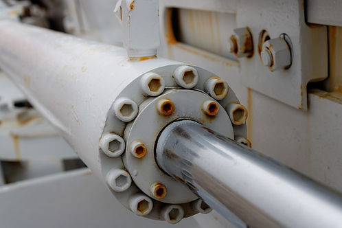
Step 3: Choose the Hydraulic Actuators
Actuators convert hydraulic energy into mechanical work:
Cylinders (Linear Motion): Choose between single-acting or double-acting cylinders based on the application.
Motors (Rotary Motion): Select hydraulic motors for applications requiring rotational power.
Sizing: Calculate the bore size, stroke length, and rod diameter for cylinders or the torque and speed for motors.
Formula example for a cylinder:
Force = Pressure X Area
Where Area is the cross-sectional area of the cylinder bore.
Step 4: Design the Control System (Valves)
Valves control the direction, flow rate, and pressure in the system:
Directional Control Valves (DCVs): Control the path of fluid flow. Common configurations include 4/3-way valves for double-acting cylinders.
Flow Control Valves: Regulate the speed of actuators by controlling the flow rate.
Pressure Control Valves: Protect the system by limiting pressure. Relief valves and pressure-reducing valves are common examples.
Tip: Use pilot-operated valves for precise control in high-pressure systems.
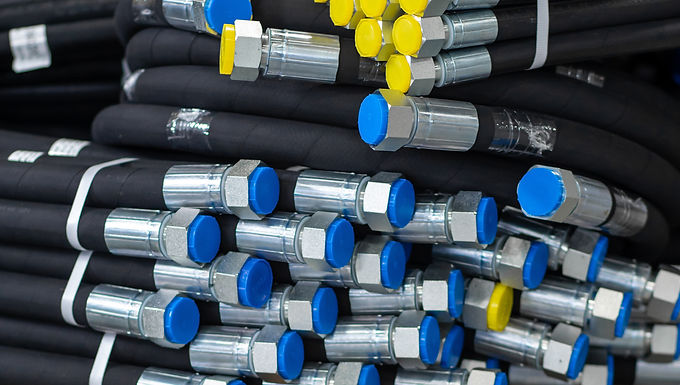
Step 5: Select and Route Hydraulic Lines
Hydraulic lines transfer fluid between components. Proper selection and routing are crucial for performance and safety:
Hoses vs. Pipes: Use flexible hoses for moving parts and rigid pipes for stationary connections.
Sizing: Ensure lines are sized to minimize pressure drop and maintain flow velocity within recommended limits (1.1 to 7.5 m/s).
Routing: Avoid sharp bends and long runs to reduce pressure loss and potential damage.
Step 6: Design the Reservoir and Filtration System
The reservoir stores and cools the hydraulic fluid, while filters keep it clean:
Reservoir Sizing: Typically, reservoirs should hold 2-3 times the system’s maximum flow rate.
Filtration: Use high-efficiency filters to remove contaminants and extend component life. Place filters on the return line and suction line for best results.
Cooling: If necessary, include heat exchangers to dissipate excess heat from the fluid.
Step 7: Include Safety and Monitoring Components
Safety is critical in hydraulic systems:
Pressure Relief Valves: Protect against overpressure by venting excess fluid.
Emergency Shut-Offs: Include manual or automatic shut-off valves for system isolation.
Sensors and Gauges: Monitor pressure, flow, and temperature to ensure safe and efficient operation.
Step 8: Create a Hydraulic Schematic
A hydraulic schematic is a visual representation of the circuit. It helps in troubleshooting and communication:
Use Standard Symbols: Follow ISO 1219 or ANSI Y32.10 standards for hydraulic symbols.
Label Components: Clearly label all pumps, valves, actuators, and lines.
Indicate Flow Paths: Show the direction of fluid flow and connections between components.
Step 9: Test and Optimise the Circuit
Once assembled, test the system to ensure it meets performance requirements:
Leak Testing: Check for leaks at connections and seals.
Performance Testing: Verify actuator speeds, forces, and pressures.
Fine-Tuning: Adjust valve settings and line routing to optimise performance.
Conclusion
Designing a hydraulic circuit is a step-by-step process that requires careful consideration of system requirements and component selection. By following these guidelines, you can create efficient, reliable, and safe hydraulic systems that meet the needs of your application. For more resources and tools, explore Lister Fluid Power’s technical guides and hydraulic calculators.
Need Expert Assistance?
Our team of technical specialists is here to help. If you have questions or need further guidance, feel free to contact us. . For more insights, check out our blog.
More Guides
Specifying Hydraulic Hose Assemblies